TN-S where they are separated 5 wire or TN-C- S. Neutral and protective functions are combined in a single conductor in a part of the system.

Earthing Arrangements Tnc Tn S Tnc S It And Tt Elec Eng World
Requires the installation of earth electrodes at regular intervals throughout the installation.

Difference between tt and tns system. Generally speaking the TN system. In this regard on TN systems the neutral point of the supply transformer is grounded only with a low impedance and it is through a protective conductor that the electrical installations masses are connected to the networks operating ground. Neutral and protective functions are combined in a single conductor throughout the system.
Throughout the system a separate protective conductor is used. TT systems require less technical input and have much lower fault currents. In a TN-S system both the neutral and protective conductors are separate within the supply and within the installation.
Normally the means of earthing is provided from the supply cable metallic sheath or other separate supply conductor. The old LEB required an electrode with a maximum resistance of 20 before connection to their PME was allowed. Put in an EV charger-like system to disconnect the supply live and the CPC on a fault.
TN-C Common ground and neutral. Whereas the DNO next door Seeboard only required that an electrode be installed there was no maximum resistance specified. With TT the consumer must provide their own connection to earth ie.
The user provides grounding with a separate ground electrode. T denotes that the star point of the source is solidly connected to earth which is usually at a location very near to the winding. By installing a suitable earth electrode local to the installation.
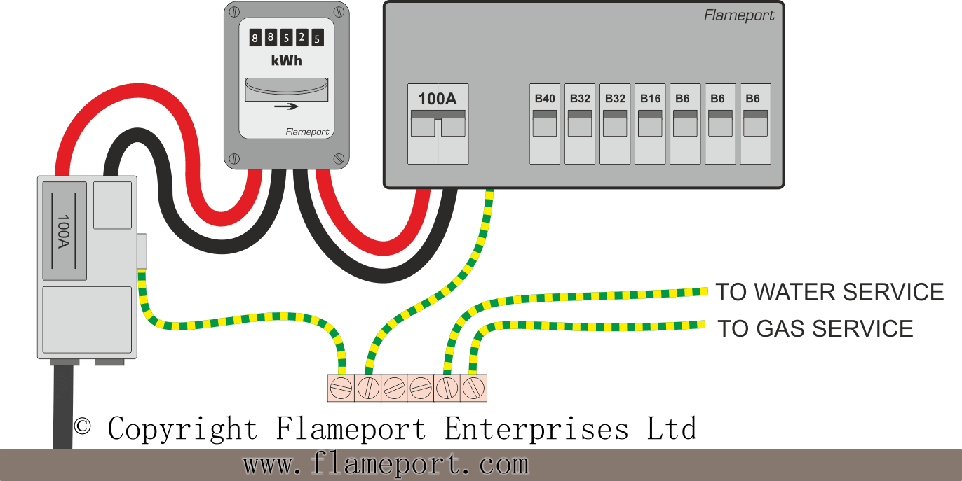
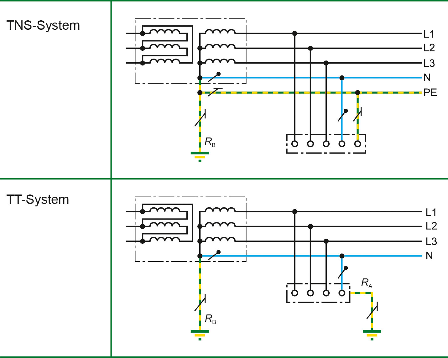
13 TT system earthing A TT system shown above has the neutral of the source of energy connected as for TN-S but no facility is provided by the distributor for the consumers earthing. TN-S system. The user gets separate ground and neutral and these are kept separate up to the socket.
The source and the load separately connected to earth there is no connection between earth and neutral too. TN-C-S system-This system has the supply neutral conductor of a distribution main connected with earth at source as protective multiple earthing. Put in impractically low Ra rods.
TN-S Separate ground and neutral. The ground is in no way connected to the electric system. With street furniture different DNOs have different requirements.
3 TN system has the advantage that in case of an insulation fault the fault voltages touch voltages are generally smaller than in TT earthing systems. In TT systems the star point is also connected to earth through a low impedance but the exposed conductive parts of the electrical installation are. The five methods are abbreviated TNC TNS TNCS TT and IT.
Many wax lyrical about the good old days of TN-S but all systems have advantages and disadvantages. The protective earth conductor is separate throughout the system. Requires that the initial check on effective tripping for the first insulation fault be carried out by calculations during the design stage followed by mandatory measurements to confirm tripping during commissioning.
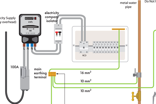
The latter is very common as it allows the single-phase loads to be supplied by phase and neutral with a completely separate earth system connecting together all the exposed conductive parts before connecting them to the PEN conductor via a main earthing terminal which is also connected to the neutral terminal. The first letter denotes the source of power from a star-connected winding. TN-C-This system is a combined PEN conductor fulfils the functions of both a PEprotective.
The neutral and protective earth conductors are combined in a single conductor throughout the system. Neutral and protective functions are combined in a single conductor in a part of the system. The impedance might be too high to rip the circuit breaker.
In TN systems the star point of the feeding transformers is connected to earth through a low impedance and the exposed conductive parts of the electrical installation are connected to the protective earth PE of the system. It is mainly North America and Northern Europe that favour TN systems. For a LV customer a TN-C system is installed between the site transformer and the premises the neutral is earthed multiple times along this segment and a TN-S system is used inside the property itself from the Main Switchboard downstream.
In a TN-C-S system the neutral and earth are combined within the supply and separate within the installation. This is due to the voltage drop in the phase conductor and the lower impedance of the PEN conductor compared with the consumer earthing in TT systems. The best way I can come up with to find out which it is without taking it apart is to measure the resistance between the neutral at the head meter or CU and the earth terminal on the head.
If you have a TN-S you will be measuring the resistance of the neutral back to the Tx and the armour from the TX back to the earth terminal. Taken across the world the most widely used system is in fact TT. The main advantage is to save conductor costs over the traditional TN-S system by not running separate N E to everywhere secondary advantage is usually a lower supply fault impedance Ze so easier to achieve fast disconnection by fuse or MCB.
The source connected to earth and the load is connected to the same earth there is TN-C where common cable is used for earth and neutral TN-S separate neutral and earth but same as sources earth TN-C-S there is common point for earth and. TT the supply. The first option may be the easy one if carefully considered at the installation time but how many existing properties will not be so isolated and how many folk will consider the PEN fault case for fitting new stuff.

Power Supply System By Surge Protection Devices Spds

Nidaamka Bixinta Awoodda Ee Qalabka Ilaalinta Sare Ee Spds

What Are Different Ac Power Systems Tn Tt It Earthing And Which One Should You Choose E Mobility Simplified Basics Of Electric Vehicles And Charging
An Introduction To Earthing And Bonding

What Are Different Ac Power Systems Tn Tt It Earthing And Which One Should You Choose E Mobility Simplified Basics Of Electric Vehicles And Charging
Erection Of Earthing Arrangements Tnc Tn S Tnc S Tt Eep

Choosing The Right Earthing System Bernard Jover Schneider Electric

Netzformen Zur Stromversorgung Ein Vergleich Bender
Power Supply System By Surge Protection Devices Spds

An Introduction To Earthing And Bonding
Tncs Supply

Sizing Main Protective Bonding Conductors Voltimum Uk

Types Of Earthing Systems Used In Electrical Installations Learning Electrical Engineering

What Are Different Ac Power Systems Tn Tt It Earthing And Which One Should You Choose E Mobility Simplified Basics Of Electric Vehicles And Charging
Tn S Tt System Bender

Power Supply System By Surge Protection Devices Spds

An Introduction To Earthing And Bonding

Types Of Earthing Systems Used In Electrical Installations Learning Electrical Engineering

Earthing System Wikipedia


Post a Comment
Post a Comment